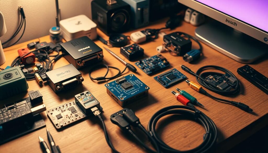
Hands-on builds put control back in the hands of users who need tailored connectivity for devices, displays, and power delivery tasks. This introduction outlines what to expect: parts lists, safety limits, signal routing basics, and practical performance targets.
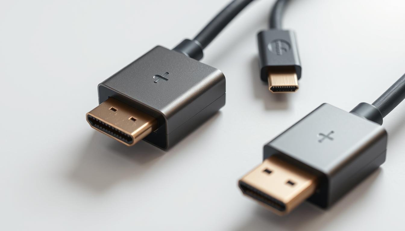
USB-C ports can carry data, video, and power when the host supports DisplayPort Alt Mode. HDMI moves high-definition audio and video to TVs, monitors, and projectors. Knowing how each standard routes signals helps teams choose the right approach for a given device or display.
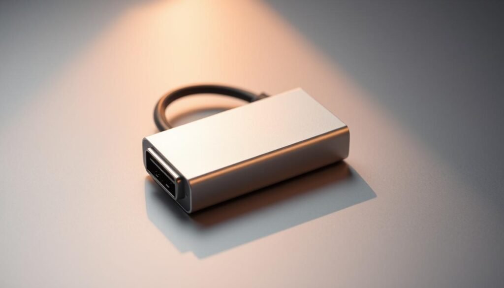
The hub also compares home builds versus off-the-shelf options and highlights risks, such as unsafe cable conversions that can harm hardware. For a focused walkthrough on a common conversion, readers can follow a step-by-step page to build a USB-C to HDMI converter.
Key Takeaways
- Single-cable solutions can deliver video, data, and power when ports support the right modes.
- Signal quality depends on converter chips, cable choice, and proper wiring.
- Safety-first practices prevent damage from improper cable or connector use.
- Home builds can save cost and allow customization for niche needs.
- Testing workflows validate refresh rates and compatibility with monitors and projectors.
Why Build Your Own Adapters?
Creating tailored connections gives engineers precise control over signal paths and enclosure fit. Home-built solutions let teams match pinouts, cable length, and shielding to specific devices and displays. That control often improves video and data reliability in tight setups.
Cost Savings And Component Reuse
Reusing spare parts cuts expenses. Salvaged cables, plugs, and simple converter boards can produce a reliable link for a laptop demo or lab bench at a fraction of retail cost.
Customization For Specific Devices And Displays
Builders can tune cable length and add strain relief to reduce loss. They can choose enclosures that dissipate heat and protect solder joints for routine presentations or a big screen setup.
Learning, Experimentation, And Skill Building
Each build teaches soldering, continuity testing, and signal basics for usb type-c and hdmi signaling. These skills clarify trade-offs between data speed and power delivery.
| Benefit | When to Choose Custom | Key Check |
|---|---|---|
| Cost | Spare parts available, low volume | Estimate parts vs retail price |
| Fit | Tight enclosures, odd pinouts | Measure connector clearances |
| Performance | Short runs, low latency video | Use spec-compliant cables and test chains |
Before starting, readers should research parts, set realistic time and quality goals, and make sure cables are rated for the intended bandwidth and current.
USB-C To HDMI Projects
A compact walkthrough explains parts, pin mapping, and the checks needed to produce stable video output from a usb-c port.
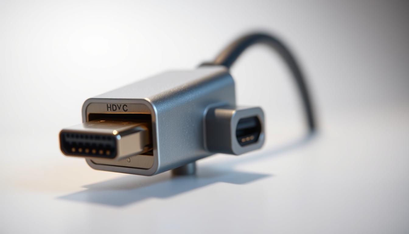
How To Build Your Own DIY USB-C To HDMI Adapter
Materials: usb-c male connector, hdmi female connector, soldering iron, wire stripper, heat shrink, and a multimeter for continuity checks.
Prepare connectors and strip insulation. Identify pin assignments from datasheets, solder matching signal pairs, and insulate each joint with heat shrink. Test between the host and display for video and audio presence.
USB-C To HDMI Wiring Diagram And Pinout Basics
Map SuperSpeed lanes, HPD (hot plug detect), and ground/shield to preserve video signals. Ground loops or poor shielding cause dropouts, so keep shields continuous and tie grounds at common points.
DisplayPort Alternate Mode And USB-C Video Output Support
DisplayPort alternate mode negotiates over the usb-c port to carry high-resolution video. Not every usb-c port supports video; make sure the host supports alt mode before building or buying a usb-c hdmi adapter.
Power Delivery, Cable Choice, And Display Settings For Reliable Video
Choose certified cables for the target resolution. HDMI 2.0 commonly supports 4K@60Hz; DP over usb-c can reach higher bandwidths with compliant cabling.
Set display settings for resolution, color depth, and refresh rate. Run a quick test plan: check boot logo visibility, EDID recognition, and stable output across cold and warm starts.
| Step | Action | Why it matters | Quick check |
|---|---|---|---|
| Prepare | Strip wires, label pins | Prevents mis-wiring and shorts | Continuity test with multimeter |
| Solder | Attach SuperSpeed pairs and HPD | Maintains signal integrity | No intermittent signal on video |
| Shielding | Connect ground and outer braid | Reduces EMI and dropouts | Stable image at target refresh |
| Final test | Boot, EDID, audio passthrough | Verifies compatibility with displays and projectors | Consistent output across reboots |
For an illustrated wiring layout and pinout details, see the full USB-C to HDMI wiring diagram. If conversions require protocol translation, choose an active unit rather than a straight-through pass; that prevents compatibility failures with devices that do not support alt mode.
SATA To USB Projects
Repurposing parts from old drive enclosures gives a cost‑effective path to connect legacy disks to modern hosts.
Repurposed bridge boards often contain the controller needed to pair a 2.5‑inch drive with a host port. Builders should map the data and power pins carefully and keep wire runs short to limit loss.

Repurposing Spare Parts
Legacy enclosure PCBs and bridge chips can create a compact adapter for portable drives. Verify the board supports UASP for better throughput versus bulk‑only transport.
Wiring Diagram And Data Transfer Tips
Match SATA data lanes and 5V power correctly. Grounding and cable management reduce crosstalk and improve sustained data transfer quality.
Advanced Techniques For Performance And Safety
Use ferrite beads, shielded short cables, and thermal relief for heavy backups. For 3.5‑inch devices, plan an external 12V supply with adequate current and protected rails.
| Topic | Key Action | Why it matters |
|---|---|---|
| Power | Verify 5V stability under load with a multimeter | Prevents drops and enumeration failures |
| Throughput | Choose UASP‑capable bridge or enclosure | Lower latency and higher sustained transfer rates |
| Validation | Run sustained copy, hash checks, SMART tests | Confirms data integrity and drive health |
| Reliability | Use certified cable and protected power | Avoids intermittent disconnects and hazards |
For detailed assembly steps and safety notes, see a step‑by‑step page on converting enclosures: SATA to USB repurposing walkthrough.
DisplayPort, VGA, Audio, And Serial Builds
The section covers practical builds for legacy and modern displays, plus audio and serial links for embedded work.
Crafting Your Own DisplayPort To DVI Adapter
Passive vs active conversion: Single-link DVI is possible when the source exposes compatible lanes. For higher resolutions, an active converter is required.
Shielding and pin mapping matter: keep shield continuity and route TMDS pairs carefully to avoid jitter on video signals.
DIY VGA To HDMI Adapter For Legacy Displays
Analog-to-digital requires an active board with proper power budgeting and heat relief. Enclosure ventilation and certified parts reduce failure risk.

Creating A Custom Audio Adapter For Clear Video Audio Paths
Preserve lip sync by keeping audio wiring length minimal and using a common ground scheme. Ferrites and foil shielding cut hum near high-current lines.
Building A USB To Serial Adapter For Embedded Projects
Choose a reputable bridge IC, add ESD diodes, and place header pinouts with strain relief. This prevents board damage and eases debugging on monitors and projectors.
- When routing DP via usb-c adapters, check if alt mode provides a straight path or if active translation is needed.
- Run an EDID and timing test matrix: conservative modes first, then increase resolution and color depth.
| Check | Why | Quick action |
|---|---|---|
| Certification | Protects host and display | Use marked parts |
| Short cabling | Reduces jitter | Keep cable runs under spec |
| Thermal | Prevents shutdowns | Vent enclosures |
For an active DP-to-VGA board option, consider a tested product such as a reliable DP to VGA converter.
OTG, Ethernet, And Thunderbolt Projects
For mobile rigs and single-board computers, adding wired Ethernet and host-mode USB can solve stability and latency issues that wireless links cause.
OTG Host Wiring For Mobile Devices And Raspberry Pi
Wiring an OTG cable requires correct orientation of the ID pin so the device assumes host mode. Keep wire runs short and protect the 5V rail to avoid brownouts when peripherals draw current.
Test enumeration by attaching a known USB mass storage or keyboard. Verify that the host supplies sufficient current and that data lines show steady link activity.
Ethernet Controller Selection And Network Stability
Choose a low‑overhead USB‑to‑Ethernet controller with UIPC or UAS support to reduce CPU load. Pay attention to ground isolation and common-mode rejection to prevent packet loss.
Run iperf tests to validate throughput and use LED link-state checks for physical diagnostics. Proper grounding keeps latency low when streaming heavy data.
Thunderbolt: Capabilities, Limits, And When Not To Build
Thunderbolt protocol complexity and certified cabling make homemade conversions risky. It can carry video, power delivery up to 100 W, and high‑speed data, but certification matters for safe output and operation with monitors and docks.
When in doubt, choose a certified commercial adapter for travel-ready reliability; custom modules are viable for low‑speed host functions but not for full Thunderbolt tunnels.

| Check | Why | Quick action |
|---|---|---|
| Host role | Ensures device enumerates peripherals | Verify ID pin wiring |
| Link speed | Confirms network performance | Run iperf throughput test |
| Power budget | Prevents brownouts | Measure 5V under load |
| Cable certification | Protects device and peripherals | Use labeled usb-c adapters or certified cable |
Safety note: stay within spec, avoid noncompliant couplers, and prefer certified parts when power delivery or video is required. Match the build to user needs and choose the safest option for high‑risk uses.
DIY Adapter Projects Guide: USB-C, HDMI, SATA, DisplayPort, And More
A staged test plan makes it simple to validate video links before a show or lab run. Start with an EDID read and confirm the host enumerates the display. Then test timing, color depth, and sweep refresh rates to spot instability early.
Check cable length and shielding first. Short, certified cables cut jitter and improve video reliability. Document display settings that produce a clean big screen image for repeatable results.
Testing Signal Integrity, Resolution, And Refresh Rates
Run a step list: EDID, low-resolution boot, full-resolution test, then audio checks. Use a known-good short cable if the link fails. Lowering resolution or refresh often restores sync while troubleshooting continues.

Common Mistakes To Avoid With USB-C, HDMI, And DisplayPort
Assuming every usb-c port supports video output is a common error. Mixing passive parts when active translation is required also causes no-signal scenarios.
“Noncompliant gender changers and uncertified cables can damage hosts and displays; always use marked, spec-compliant parts.”
Safety And Compliance: Power Delivery, Certified Cables, And Spec Limits
Power delivery can reach 100 W on compliant links, but the cable and port must support it. Look for USB iconography and vendor markings to confirm certification.
Real-World Use Cases: Retro Gaming, Raspberry Pi, And Presentations
For retro gaming scalers, Raspberry Pi rigs, or conference-room setups, choose the path that matches the display’s capabilities. DP alt mode may allow higher resolutions (up to 8K60) while standard hdmi often peaks at 4K60 via HDMI 2.0.
| Check | Action | Why it matters |
|---|---|---|
| EDID | Read with tool or OS | Ensures supported modes are known |
| Cable | Swap for certified short cable | Identifies cable-related jitter |
| Power | Verify PD profile and wattage | Prevents brownouts during presentations |
Field kit: a spare usb-c hdmi adapter, a short certified cable, strain relief, and a quick checklist. This small set keeps video and audio video links reliable on the road.
Final Thoughts
A careful, spec-aware build yields reliable connections that stand up in labs and conference rooms.
Properly designed adapters made with certified components and good workmanship deliver consistent output and protect each device and display. USB‑C ports that support DisplayPort Alt Mode can carry power and high‑resolution video in one cable; unsafe female‑to‑male couplers may harm hardware, so avoid noncompliant parts.
Builders should test video, audio, and stability with a simple checklist. Keep a small field kit with short cables, spare hdmi adapters, strain relief, and documented pinouts to cut downtime at the end of a demo.
To start a focused usb-c hdmi adapter build, review step‑by‑step materials and tests at building your own USB‑C to HDMI. A strong, practical checklist and recorded settings speed future repairs and preserve quality.
FAQ
How can one ensure a USB type-c port supports video output before building a cable?
They should check the device specifications for DisplayPort Alternate Mode or HDMI Alt Mode support. Manufacturers like Apple, Dell, and Lenovo list video-capable ports in product docs. If documentation is unclear, testing with a known good certified cable and monitor reveals whether the port carries audio-video signals.
What role does power delivery play when connecting a laptop to a monitor?
Power delivery negotiates voltage and current between host and sink so the laptop can charge while sending video. Using a PD-capable cable and a power supply that matches the laptop’s requirements avoids underpowering the system or stressing cables. Always use certified PD hardware to reduce risk.
Which cable choices preserve maximum video quality for 4K at 60Hz?
High-bandwidth cables that meet HDMI 2.0 or DisplayPort 1.4 specifications are necessary. Longer runs need active cables or signal boosters to maintain integrity. Certified cables from brands such as Belkin, Anker, and Cable Matters minimize signal degradation.
Is passive wiring sufficient for USB type-c to HDMI conversion?
Passive wiring only works if the host natively outputs HDMI signals via the port’s alternate mode. Most implementations require an active bridge chip that converts DisplayPort streams to HDMI. Relying on passive wiring risks no signal or poor compatibility.
How does one test signal integrity and refresh rates after assembly?
Use a test monitor or capture device that reports resolution, color depth, and refresh rate. Software tools like Monitor Asset Manager or the monitor’s on-screen display can confirm timing. If rates or colors are wrong, check solder joints, grounding, and cable shielding.
What safety precautions protect devices when working with SATA to USB conversions?
Ensure proper power sequencing and use level shifters when interfacing different voltages. Isolate spinning drives from hot-plug events and include ESD protection. Use enclosures with proper ventilation and run health checks with CrystalDiskInfo or smartctl after connecting.
Can a Thunderbolt port be treated the same as a standard USB type-c port for video and data?
Thunderbolt combines PCIe and DisplayPort streams and supports higher bandwidth than standard type-c. Some Thunderbolt ports will accept USB-C peripherals, but not all USB-C hosts expose Thunderbolt features. Use Thunderbolt-certified cables and check host capability for full functionality.
What common mistakes reduce display compatibility when making custom cables?
Frequent errors include misrouting ground and shield, omitting necessary configuration resistors, using incorrect impedance, and skipping active conversion where required. These mistakes cause no signal, flicker, or reduced resolution. Follow signal schematics and reference designs from chip vendors.
How should one approach legacy conversions like VGA to HDMI for presentations?
VGA is analog and requires an active scaler to convert to digital HDMI. Choose a converter that supports the target resolution and includes audio embedding if needed. Test with the actual projector or display to confirm color and timing before critical events.
Are there compliance concerns when building cables for public or professional use?
Yes. Power delivery and high-speed video specifications have safety and EMC requirements. For public or commercial deployments, use certified cables and modules that meet USB-IF, HDMI Forum, or VESA standards to avoid liability and interference issues.
How can one improve throughput for SATA to USB single-board computer setups?
Use USB 3.1 Gen 2 or USB 3.2 hosts, choose UASP-capable bridge chips, and employ high-quality short cables. Ensure the drive firmware is up to date and the host provides adequate power. Optimizing file system alignment and disabling unnecessary write caching can also help.
When is it necessary to use active cables or signal boosters for long runs?
For runs beyond typical passive limits—often over 3 meters for high-bandwidth HDMI or DisplayPort—active cables maintain signal amplitude and timing. Use boosters when encountering intermittent artifacts, loss of handshake, or lowered refresh rates on long links.
What troubleshooting steps help when a display shows no signal after connecting?
Confirm the source supports video over the port, verify cable continuity and pinouts, test with a known-good monitor and cable, and inspect solder joints and connectors. Check power delivery negotiation and try different display modes or drivers on the host.
How does audio pass through when converting between different video standards?
Digital standards like HDMI and DisplayPort carry embedded audio. When converting from analog sources or between standards, an audio embedding or extraction stage is required. Ensure the converter supports the desired audio formats and channel counts.
What are real-world use cases where custom connectivity is most valuable?
Custom links shine in retro gaming with legacy displays, integrating Raspberry Pi into home setups, bespoke presentation rigs, and lab testing where unusual pinouts or mixed signals exist. Tailored cables reduce bulk and adapt mismatched ports effectively.