Old tech adapter projects bring outdated devices into present-day workflows by unifying small connector types into a clear build plan. Many computers and monitors still support DP, HDMI, DVI, and VGA, so selecting the right connector matters for signal integrity.
They plan each step: choose passive versus active conversion, verify digital versus analog paths, and confirm that a USB-C port supports video via DisplayPort or Thunderbolt Alt Modes before relying on it.
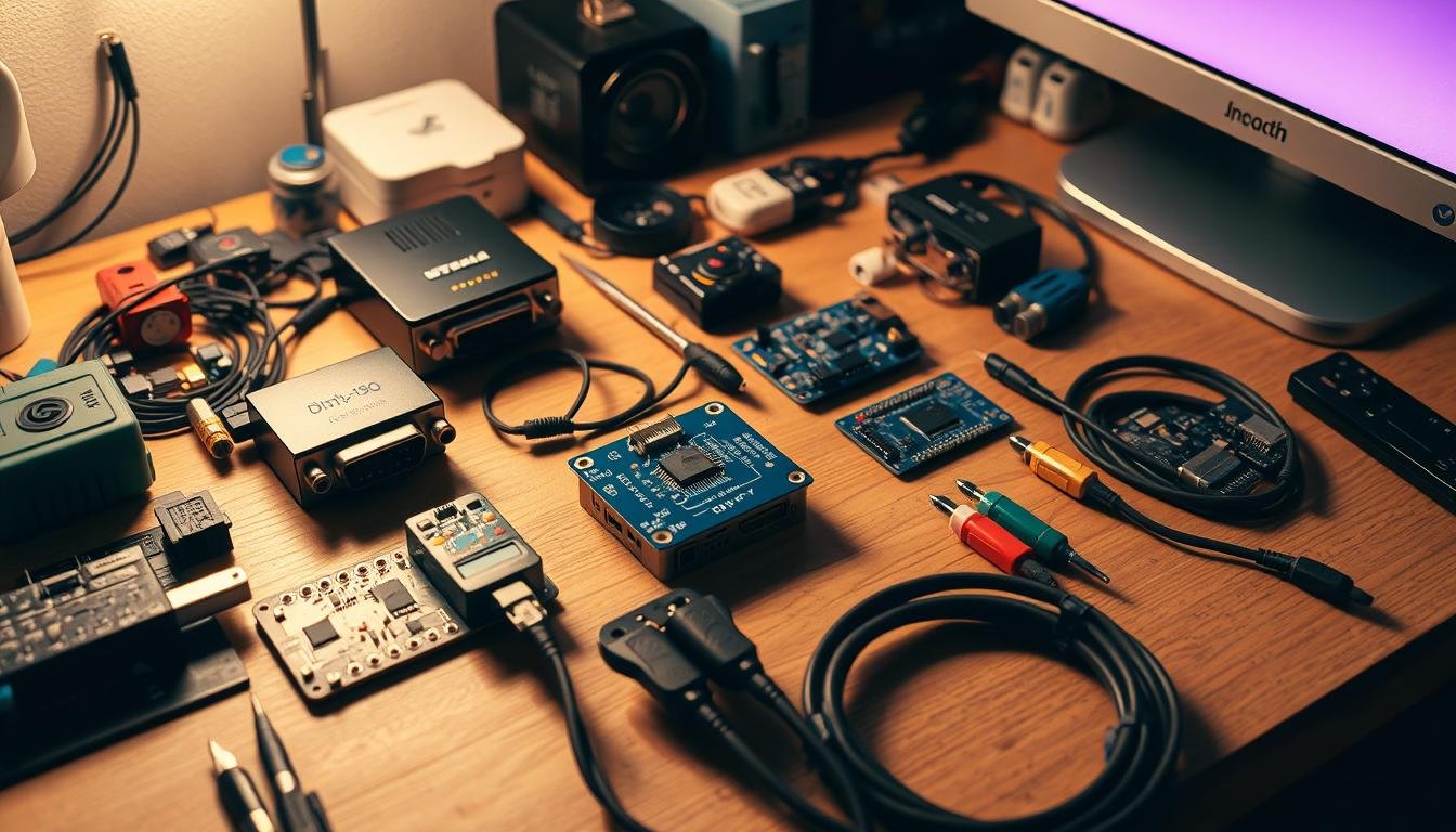
The introduction previews hands-on tasks like stripping cable jackets, identifying RGB and ground, soldering, applying heat shrink, and running continuity checks with a multimeter. It also notes networked testing options using a Raspberry Pi video capture setup for end-to-end validation.
Readers will find a roadmap that ties each project to specific connectors, power considerations, and testing steps so teams can document repeatable outcomes and avoid common failures.
Key Takeaways
- Understand when passive parts suffice and when an active converter is required.
- Pick the correct connector and cable to protect signal integrity and power.
- Follow soldering, insulation, and continuity tests to prevent faults.
- Use a Raspberry Pi capture workflow for networked video validation.
- Keep a clear parts list and verify monitor input and computer drivers before testing.
- See a practical VGA-to-HDMI example for technique details: VGA-to-HDMI example.
Understand Legacy Video, Audio, And Serial Connectors For Old Tech Adapter Projects
Knowing whether a port carries analog or digital signals directs whether a passive cable or an active converter is needed. Dell categorizes connectors by signal type: VGA, S-Video, and Composite are analog while HDMI and DisplayPort are digital. DVI may be DVI-A, DVI-D, or DVI-I, and the dvi connector pinout determines compatibility.
Confirm whether a usb-c port supports Alt Mode (DisplayPort or Thunderbolt). A usb-c port without Alt Mode cannot carry video, so check OEM documentation or the computer’s specifications before choosing cables or converters.
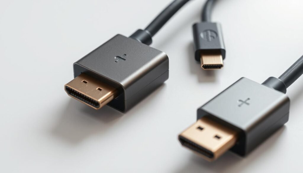
Catalog common connector shapes and version limits for HDMI and the displayport connector family to match resolution and refresh needs. Note that many converters are directional; choose the correct source-to-sink mapping to avoid no-video outcomes.
“Audit ports on desktops, all-in-ones, and laptops and save the documentation for repeatable installs.”
- Audit ports by device and record supported versions and power needs in documentation.
- Plan audio paths: HDMI and DisplayPort carry embedded audio, while analog paths often need separate audio wiring.
- Handle wires carefully when re-terminating to prevent shorts and power issues.
For help picking the right fit, see this short article on navigating common choices: navigating the adapter maze.
Hands-On Build: DisplayPort To DVI Legacy Adapter DIY
Before cutting any jacket, the installer should confirm pin compatibility and plan strain relief to protect signals and power paths. This ensures the connector mapping matches the monitor and source, reducing the chance of a black screen or intermittent output.

Tools, Materials, And Safety
They will use a DisplayPort male, a DVI female, quality cable, soldering iron with solder, heat shrink, and a multimeter. ESD wrist straps, tip temperature control, and a well-ventilated area protect the device and operator.
Pinouts, Cable Prep, And Clean Soldering
Strip the outer insulation, identify RGB and ground wires, and match each conductor to the correct dvi connector pin. Clean, shiny solder joints and correct alignment reduce interference and preserve video signals.
Insulation, Strain Relief, And Continuity Testing
Insulate each joint with heat shrink and route wires to avoid crosstalk. Use a multimeter for continuity checks to confirm no shorts or opens before final assembly.
Final Assembly And First-Power Guidelines
Apply strain relief, label the cable mapping, and connect the chain with devices off. Power on the computer and monitor, then verify the video handshake and stable output.
“Document pinouts and cable color mapping so future repairs and replications are quick and error-free.”
| Step | Key Action | Tool | Check |
|---|---|---|---|
| 1 | Confirm pin compatibility | Datasheet / Visual | Pin map matches monitor |
| 2 | Prep cable & identify conductors | Wire stripper, microscope | RGB and ground labeled |
| 3 | Solder and insulate joints | Soldering iron, heat shrink | No cold joints, secure strain relief |
| 4 | Continuity & first power | Multimeter | All pins continuous; video stable |
For cable and conversion options that work with many setups, see this recommended cable selection.
Configure, Cable, And Test Your DIY Adapters On Monitors, GPUs, And Operating Systems
Before powering any devices, the team maps each source and sink to pick the cleanest cable path for reliable video handshakes.

Selecting The Right Cable Path: DisplayPort, HDMI, DVI, VGA, Or USB-C Alt Modes
They verify each port on the computer and monitor, confirm whether the usb-c port supports Alt Mode, and choose cables that match directionality. When ports differ, they pick the correct converter or active unit since many are not bi-directional.
Practical step: plug the hdmi cable or DisplayPort/DVI/VGA lead before power-up, set the monitor input, then power devices to reduce handshake issues.
Operating System Display Settings: Resolution, Refresh Rate, And Mirroring
After enumeration in the operating system, the team updates GPU drivers, sets resolution and refresh to supported values, and chooses mirror versus extend. They test color depth and scaling and reopen settings after firmware updates to confirm stable video.
“If the screen stays blank, power-cycle the monitor and re-seat the connector until the display enumerates in the OS.”
- Test with short, known-good cable runs first; escalate length if stable.
- Use a usb cable for powered dongles when needed, or add external power to avoid bus overload.
- Document screen settings and capture screenshots of display properties for repeatable setups.
| Check | Action | Expected Result |
|---|---|---|
| Port Verification | Confirm source/sink types and usb-c Alt Mode | Correct cable path chosen |
| Plug Order | Connect video cable then power devices | Reduced handshake failures |
| OS Settings | Set resolution, refresh, and mirror/extend | Stable display and correct scaling |
| Power & Testing | Try short cables, use external power if needed | Reliable signal; logged configuration |
For a tested USB-C to VGA option, see the USB-C to VGA cable that simplifies validation on laptops and desktops.
Unify Smaller Adapter Types: Audio, Serial, And Composite/Component Builds
Teams should standardize how they handle small connectors so parts, power, and pin maps stay consistent across systems. This reduces repeated troubleshooting and speeds deployment for workbenches, test rigs, and field kits.

Audio Adapters: RCA, 3.5 Mm, And Simple Grounding/Shielding Practices
Proper grounding and shielding prevent hum and crosstalk on RCA and 3.5 mm runs. Use twisted pair for balanced runs and keep unbalanced leads short.
When impedance mismatch appears, pick active converters or small in-line isolators and plan power for preamps to avoid ground loops between a laptop and powered speakers.
Serial Adapters: USB To Serial Fundamentals And Wiring Considerations
Confirm voltage levels (3.3V vs 5V), pin mapping, and handshake lines before wiring. Label each wire and document the connector mapping to ensure reliable signals to the computer or microcontroller.
“Not all converters are bi-directional; verify direction and power needs before assuming reversibility.”
- Standardize parts and labeling to match ports and power plans.
- Route cables to minimize strain and label connectors for quick troubleshooting.
- Refer to a common plugs index for connector shapes and names: common plugs and connectors.
| Type | Common Issue | Action |
|---|---|---|
| RCA Composite | Color/luma mismatch, no HD | Use correct yellow input; expect analog limits |
| Component (YPbPr) | Color alignment, separate sync | Match red/green/blue and set monitor input |
| USB → Serial | Voltage/pin mismatch | Verify TTL level, map TX/RX, add ground |
| 3.5 mm | Hum/ground loop | Use isolation or balanced cabling; add power if needed |
Legacy Adapter DIY Guide: DisplayPort, VGA, Audio, Serial Builds
This hub consolidates conversion paths for video, sound, and serial wiring so teams can pick the right route quickly.
The section explains when an analog-to-digital path needs an active converter and external power. It shows how to size the converter and route the cable to the correct port on the graphics card or device.

DIY VGA To HDMI And DVI Options: Directionality, Converters, And Power
For VGA-to-HDMI or VGA-to-DVI, an active unit is required to translate signals. Many of these units also need a USB or barrel power input to run the scaler. The article lists how to pick converters that match monitor resolutions and the card output.
Raspberry Pi-Powered Capture And Control Concepts For Old Tech Adapter Projects
PiKVM V2 on a Raspberry Pi 4 (2GB) with an HDMI‑CSI bridge (TC358743) gives low-latency 1080p@50 Hz capture. Flash the memory card with PiKVM OS, connect HDMI capture to the target, OTG to host USB, and Ethernet to the network.
“Change the default web UI and root passwords immediately.”
Link To Each DIY Build: DisplayPort→DVI, VGA→HDMI, USB→Serial, Custom Audio
This hub links to core conversion pages and integrates capture feedback into your test checklists. For additional conversion options see conversion options.
Troubleshooting And Compatibility: Connectors, Directionality, And Known Limitations
When video fails, begin with basic signal verification and simple reseating steps. A methodical no-video triage starts by verifying whether the cable carries digital or analog signals and if any converter between them is powered and directional.

Digital Vs. Analog Signals, Adapter Direction, And No-Video Scenarios
Confirm Signal Domains: Check whether the computer and monitor expect digital or analog signals. Crossing domains without an active converter or proper power causes no video.
Verify Direction: Many converters are not bi-directional. Swap to a known-good dvi adapter or short hdmi lead to isolate direction and confirm the monitor enumerates.
Resolution Caps, Motherboard Quirks, And Cable Orientation Checks
Know Device Limits: Some capture units top out at 1920×1080@50 Hz. Mismatched refresh or EDID can keep the screen blank even if cabling is correct.
OEM motherboards may block BIOS capture or redirection. Check firmware version and use desktop-specific fallbacks when BIOS capture fails.
Cable Orientation: For CSI ribbons and small connectors, always power down before reseating. Incorrect orientation or hotplugging often causes intermittent failures.
Network And Access Steps For Headless Test Benches
IP Discovery & Remote Access: Find device IP via the router UI, arp-scan, or Angry IP Scanner. Change default credentials immediately to secure access.
For PiKVM systems, run diagnostics: use dmesg | egrep ‘tc35|1-1.4|uvc’ and systemctl status kvmd-tc358743 to confirm the CSI bridge is recognized.
“If no display appears, verify cable orientation and re-seat with the power off.”
- Validate correct monitor input, reseat connections, power-cycle chain, and check OS settings for supported modes.
- Use a short known-good cable and monitor early; then extend length to identify intermittent issues.
- Document each device, port, cable, and power source for repeatable support and faster troubleshooting.
| Issue | Quick Check | Action |
|---|---|---|
| No Video | Port type & converter direction | Confirm digital/analog match; try known-good dvi adapter |
| Intermittent Signal | Cable length & power | Use shorter leads; verify power supply and USB power feeds |
| Capture Not Working | CSI ribbon & system logs | Power down, reseat CSI; run dmesg and systemctl checks |
| Headless Access | IP unknown / default creds | Discover IP via router or scan; change admin/admin immediately |
For step-by-step setup and supported connection information, see Dell’s instructions to connect a monitor to a PC. Proper documentation and power checks are often the fastest path to resolved issues and reliable support.
Conclusion
Wrap-Up, This article closes with clear, actionable steps to make video work predictable across computer and monitor pairings.
Choose Correct Connectors: Match digital or analog paths, confirm directionality, and pick the right cable and power approach to avoid no-signal outcomes.
Validate Quickly: Do a short pass with a known-good cable and a test pattern on the monitor before scaling to longer runs.
Use the linked DisplayPort→DVI, VGA→HDMI, USB→Serial, and Custom Audio pages to jump to the exact procedure needed. Standardize documentation, keep firmware and driver records, and store parts and supplier information centrally for repeatable support.
For labs adding capture, note the Pi-based option limits to 1080p@50 and requires secure configuration and updated credentials.