Building your own DIY USB to HDMI adapter is a great way to learn about signal conversion while creating a useful tool for connecting your devices to HDMI displays. Whether you want to connect a laptop, smartphone, or tablet to a TV or projector, creating your own adapter offers a cost-effective and customizable solution. In this guide, we’ll walk you through the process of making your own adapter, from understanding the technology to assembling the components and troubleshooting common issues. Let’s dive into the step-by-step instructions and start building!
Materials Needed
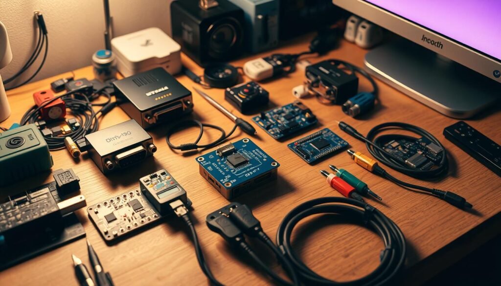
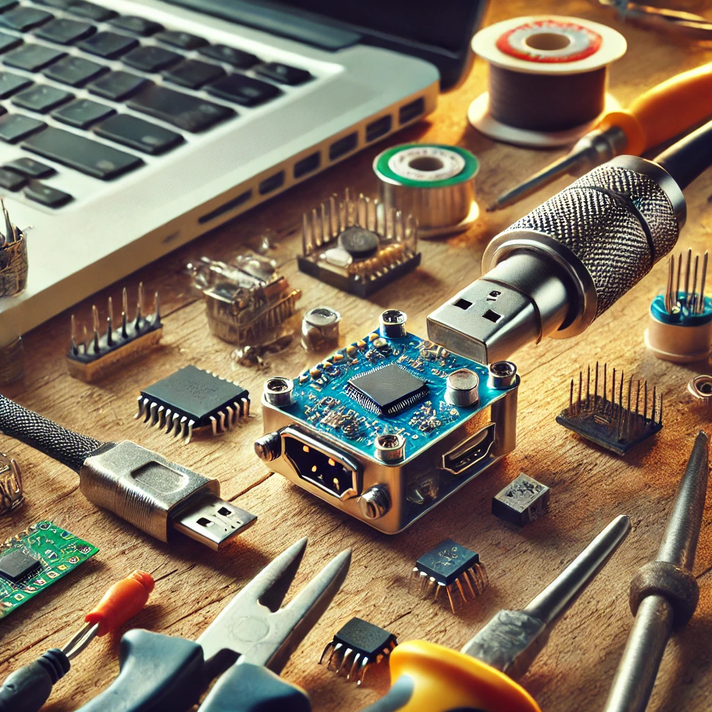
Before you start building your USB to HDMI adapter, it’s essential to gather the following materials:
- USB Cable (USB-A or USB-C depending on your device)
- HDMI Male Connector
- Signal Conversion Chip (USB to HDMI signal converter chip)
- Printed Circuit Board (PCB) or Breadboard
- Soldering Iron and Solder
- Heat Shrink Tubing or Electrical Tape
- Wire Stripper
- Multimeter (for testing connections)
- Microcontroller (optional, depending on the complexity of the design)
Exploring the Technology Behind USB to HDMI Signal Conversion
When building a DIY USB to HDMI adapter, it’s important to understand the underlying technology that enables the conversion of a USB signal to an HDMI signal. The process of converting these two different types of data involves several steps, and understanding how the technology works can help ensure a successful build. This section dives into the core principles of USB to HDMI signal conversion, shedding light on how data is processed and transmitted.
How USB and HDMI Signals Differ
Before we can dive into the signal conversion process, let’s first understand how USB and HDMI signals differ:
- USB Signal: USB (Universal Serial Bus) is primarily designed for data transfer between devices such as computers, smartphones, and peripherals. USB signals carry data in packets, and they are optimized for low-latency communication between devices rather than high-resolution video and audio output.
- HDMI Signal: HDMI (High-Definition Multimedia Interface) is a digital video/audio standard designed specifically for high-definition video and audio transmission. HDMI signals are used to connect computers, media players, gaming consoles, and other devices to high-definition displays like TVs, monitors, and projectors. HDMI carries both video and audio signals in parallel, making it ideal for entertainment and multimedia setups.
While USB is used for a wide range of applications, HDMI is specialized for multimedia content. The task of converting a USB signal to HDMI involves converting the digital data from the USB port into a format that HDMI displays can understand, including both video and audio components.
The Role of the Signal Conversion Chip
At the heart of every USB to HDMI adapter is the signal conversion chip. This chip is responsible for the most critical task: transforming the USB data into HDMI-compatible video and audio signals. The conversion process can be broken down into several steps:
- Data Transfer: When you plug a USB-C or USB-A cable into a device, it sends digital data through the USB port. The signal conversion chip receives this data and begins the process of preparing it for video output.
- Signal Processing: The chip processes the data from the USB port, which is usually in the form of compressed video and audio. The chip decodes the data, separating the audio and video information.
- Video Encoding: Once the signal is decoded, the chip encodes the video and audio data into a format compatible with HDMI. This involves converting the video into a digital signal that can be displayed on an HDMI-connected screen.
- Audio Processing: In addition to video, the signal conversion chip also handles the audio signals. These signals are encoded into digital audio formats compatible with HDMI, ensuring synchronized audio and video output.
- Transmission to HDMI: After the chip has processed and encoded both video and audio, it sends the signals to the HDMI port. The HDMI port then transmits these signals to the connected display (such as a TV, monitor, or projector).
DisplayPort Alternate Mode (DP Alt Mode)
One key feature of USB-C ports that makes this process possible is DisplayPort Alternate Mode (DP Alt Mode). Not all USB-C ports support DP Alt Mode, which is a crucial factor in enabling video output through a USB-C to HDMI connection.
- DP Alt Mode: This is a feature of USB-C that allows it to carry video signals, just like the DisplayPort standard. In DP Alt Mode, the USB-C port can transmit video signals, making it possible to connect to HDMI displays without needing a separate video output port.
The signal conversion chip takes advantage of DP Alt Mode by receiving the video data from the USB-C port and converting it into an HDMI-compliant signal. Without DP Alt Mode, USB ports would only carry data signals, making it impossible for a USB port to output video.
The Importance of the USB to HDMI Chipset
The USB to HDMI signal conversion chip is the central component that bridges the gap between USB and HDMI technology. There are various types of chips available, and each chip offers different capabilities. Some important factors to consider when choosing a chipset include:
- Resolution Support: Not all chips can handle high-definition video resolutions. If you need to support 4K video output, ensure that the chip you choose can handle higher resolutions and frame rates.
- Video Compression: Some chips use video compression to reduce the amount of data being transferred, which can affect image quality. Choose a chip that supports uncompressed video if quality is a priority.
- Audio Capabilities: Ensure that the chip can also handle audio output via HDMI. Some chips are only capable of video output, while others can transmit both video and audio signals.
Why Understanding Signal Conversion Matters
Understanding the USB to HDMI signal conversion process not only helps you appreciate the complexity behind the DIY adapter, but it also gives you more control over the build. By knowing how the signals are processed, you can make informed decisions when selecting components like the signal conversion chip, USB cable, and HDMI connector.
For example, if you need to connect your USB-C-enabled laptop to a 4K TV, you’ll need a chip that supports 4K resolution. Similarly, if you plan to use your adapter for presentations, you’ll want a chip that ensures audio-video synchronization to avoid lag.
Putting Theory into Practice: Building Your USB to HDMI Adapter
Building a DIY USB to HDMI adapter is not just about following a set of instructions—it’s about understanding the underlying technology that makes the connection possible. By exploring the way the USB signal is converted into HDMI format, you gain a deeper appreciation for the complexity of video output technology. Armed with this knowledge, you’ll be better equipped to troubleshoot, customize, and optimize your DIY adapter for the best performance.
Understanding the technology behind the signal conversion process ensures that you can confidently select the right components and create a high-quality, reliable USB to HDMI adapter that meets your needs.
Step-by-Step Guide to Building Your USB to HDMI Adapter
Step 1: Prepare the USB Cable
The first step in your DIY adapter project is preparing the USB cable. Here’s how you do it:
- Use a wire stripper to remove about 2 inches of insulation from the USB cable to expose the four internal wires: Red (Vbus), Black (Ground), White (D+), and Green (D-).
- Carefully separate the wires and strip the ends to expose the copper for soldering.
This will allow you to connect the USB cable to your signal conversion chip and eventually to the HDMI connector.
Step 2: Prepare the HDMI Connector
Now, take the HDMI male connector and prepare it for wiring:
- Strip off the insulation from the HDMI connector’s wires.
- Using a soldering iron, carefully connect each of the exposed USB wires to their corresponding pins on the HDMI connector. The Vbus (red wire) connects to Pin 1 (Power), the Ground (black wire) goes to Pin 17, and the D+ (white wire) and D- (green wire) connect to the appropriate data pins on the HDMI side.
Make sure your soldering is clean, as improper connections will lead to display issues.
Step 3: Solder the Signal Conversion Chip
The signal conversion chip is the heart of your USB to HDMI adapter. It is responsible for converting the USB signal into an HDMI-compatible signal that can be displayed on your screen. Follow these steps:
- Solder the red and black wires (Vbus and Ground) from the USB cable to the power and ground pins on the signal conversion chip.
- Solder the white and green wires (D+ and D-) from the USB cable to the data pins on the chip. These pins are responsible for transmitting video and audio data to the HDMI connector.
- Double-check all connections for correct placement to ensure proper functionality.
Step 4: Assemble the Components
Now that the signal conversion chip is connected, it’s time to assemble the components:
- If you’re using a PCB, solder all components securely to the board.
- If you’re using a breadboard, carefully place all components on the breadboard and make the necessary connections using jumper wires.
- Once all components are in place, use heat shrink tubing or electrical tape to insulate any exposed wires or connections. This will help prevent short circuits and protect your components.
Step 5: Test the DIY USB to HDMI Adapter
Now that your USB to HDMI adapter is assembled, it’s time to test it. Here’s how:
- Connect the USB-A or USB-C end of the adapter to your device (such as a laptop or smartphone).
- Plug the HDMI end into your HDMI-compatible display (TV, monitor, or projector).
- Power on both devices, and you should see the output from your device on the screen. If the image does not appear, check your connections, the USB port’s compatibility, and make sure the display is set to the correct HDMI input.
Troubleshooting Tips
If you encounter issues while testing the adapter, here are some troubleshooting tips:
- No Signal: Ensure that the USB-C port on your device supports DisplayPort Alternate Mode, as this is required for video output. If your device doesn’t support this mode, the adapter won’t work.
- Poor Video Quality: If the video is fuzzy or pixelated, ensure that the signal conversion chip supports higher resolutions like 1080p or 4K and that your cables are high-quality.
- Audio Issues: If the HDMI output works but there’s no sound, make sure the HDMI connector supports audio transmission. You might need to adjust the audio settings on your device or the HDMI-connected display.
Final Thoughts: Bringing Your USB to HDMI Adapter to Life
Understanding the technology behind the USB to HDMI signal conversion is a critical first step when building your own DIY adapter. With the knowledge of how USB data is transformed into HDMI-compatible signals, you’re well-equipped to choose the right components and tackle the project with confidence. By following the detailed instructions, you can create a high-quality, functional USB to HDMI adapter that suits your specific needs—whether for gaming, presentations, or media streaming.
Now that you understand the technical foundation, it’s time to put this knowledge into practice. In the following sections, we will guide you through every step of the build, ensuring that your DIY USB to HDMI adapter functions optimally. From wiring and soldering to troubleshooting and testing, your journey to creating a customized tech solution begins now!
Additional Resources
- Understanding USB-C: The Future of Connectivity
- Learn more about USB-C technology, its versatility, and its growing role in video output and high-speed data transfer.
- USB to HDMI using just a cable
- This article provides troubleshooting tips for when your DIY USB to HDMI adapter doesn’t work as expected, helping you resolve common issues quickly.
These additional resources provide further insights into USB-C technology and solutions for troubleshooting your DIY adapter, enhancing your overall understanding and success in completing your project.